Description
Select the Defaults tab of the Panels to set default values for various parameters to be used during the creation of any new entities after the default value has been set or changed. Settings on the Defaults panel do not impact existing entities.
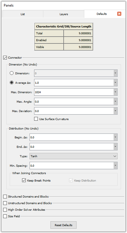
The Characteristic Grid/DB/Source Length information is displayed at the top of the Defaults panel. This helps you decide whether your default settings are suitable for your geometry or not.
The Defaults panel is logically broken up into four groups of settings: those that affect new connectors, those that affect new structured domains and blocks, those that affect new unstructured domains and blocks, and finally, those that affect the size field. This sub-section only provides a general overview of the settings available as defaults with references to their primary descriptions elsewhere in this User Manual. Any commands unique to the Defaults panel are explained here.
Note: Changing default values does not change entities which have already been created. New defaults only affect those entities newly created after the defaults change.
Connector
The commands inside the Connector frame are organized in two sub-frames: Dimension and Distribution.
The Dimension frame provides default settings for connector Dimension, Average Δs, Max. Dimension, Max. Angle, and Max. Deviation.
The default number of grid points is calculated based on the definition of Dimension or Average Δs. If the Max. Angle and/or Max. Deviation parameters are specified, points may be added to the new connectors in order to satisfy the definition of the mentioned parameters. Max. Dimension is unique to the Defaults panel and sets a dimension cap for all new connectors. This setting only affects use of the Average Δs, Max. Angle and Max. Deviation options since otherwise connector dimensions using these settings would be unlimited.
Note that the uses of Max. Angle and Max. Deviation are also described in detail in the Dimension, Distribute, and Solve sections.
The Use Surface Curvature parameter is used to refine the connector being created based on the curvature of its underlying database surface. If this option is checked on, Fidelity Pointwise computes the curvature of the underlying database surface at each connector location, and in conjunction with the Max. Angle and Max. Deviation options, refines the connector as needed. If Automatic is chosen as the default distribution function Type, the capability of Use Surface Curvature is extended to the generation of a connector spacing size field which takes into account database and source entities in the proximity of newly created connectors as well as the Min. Spacing parameter and the size field Background Spacing and Decay parameters. See the Distribute, Functions description for more details.
The Distribution frame provides default settings for Begin. Δs, End. Δs, and grid point distribution Type. These settings are described in detail for the Distribute section. Below Type is a field to enter a Min. Spacing that is used in conjunction with the Automatic distribution function. More information on the Automatic distribution function and Min. Spacing can be found under Distribute, Functions. Unique to the Distribution frame is the ability to turn off the default behavior of automatically adding break points at the common node where connectors are joined. This is done by unchecking the Keep Break Points option. When Keep Break Points is unchecked, Keep Distribution becomes available and is on by default. With Keep Distribution checked on and Keep Break Points unchecked, a General distribution results in joined connectors without interior break points. If neither option is checked on, the default Tanh distribution results in joined connectors with no interior breakpoints and equal spacing.
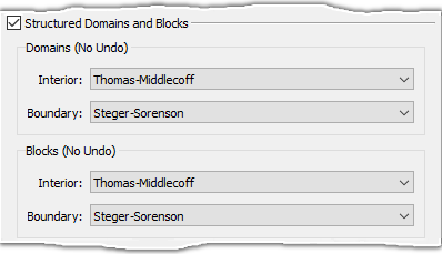
Structured Domains and Blocks
The Structured Domains and Blocks frame provides default settings for Interior and Boundary control functions for both structured domains and blocks. These settings are described in detail in the Attributes Tab sub-section within the Structured Domains & Blocks section.
Unstructured Domains and Blocks
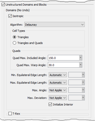
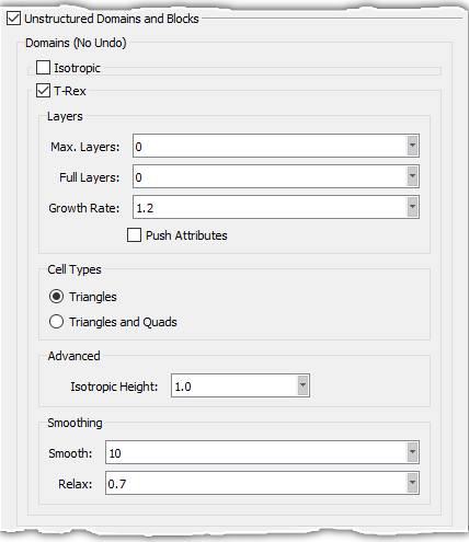
The commands inside the Unstructured Domains and Blocks frame are organized in three major sub-frames: Domains, Blocks, and T-Rex Boundary Conditions. The Domains frame (shown below) provides default settings for the isotropic and T-Rex attributes for newly created domains. These attributes are described in detail in the Attributes Tab and T-Rex Tab sub-sections respectively. These sub-sections are located within the Unstructured Domains section.
Unique to the Defaults panel is the Initialize Interior checkbox for unstructured domains (shown in left image below). When Initialize Interior is unchecked, no interior points are inserted into newly created unstructured domains.
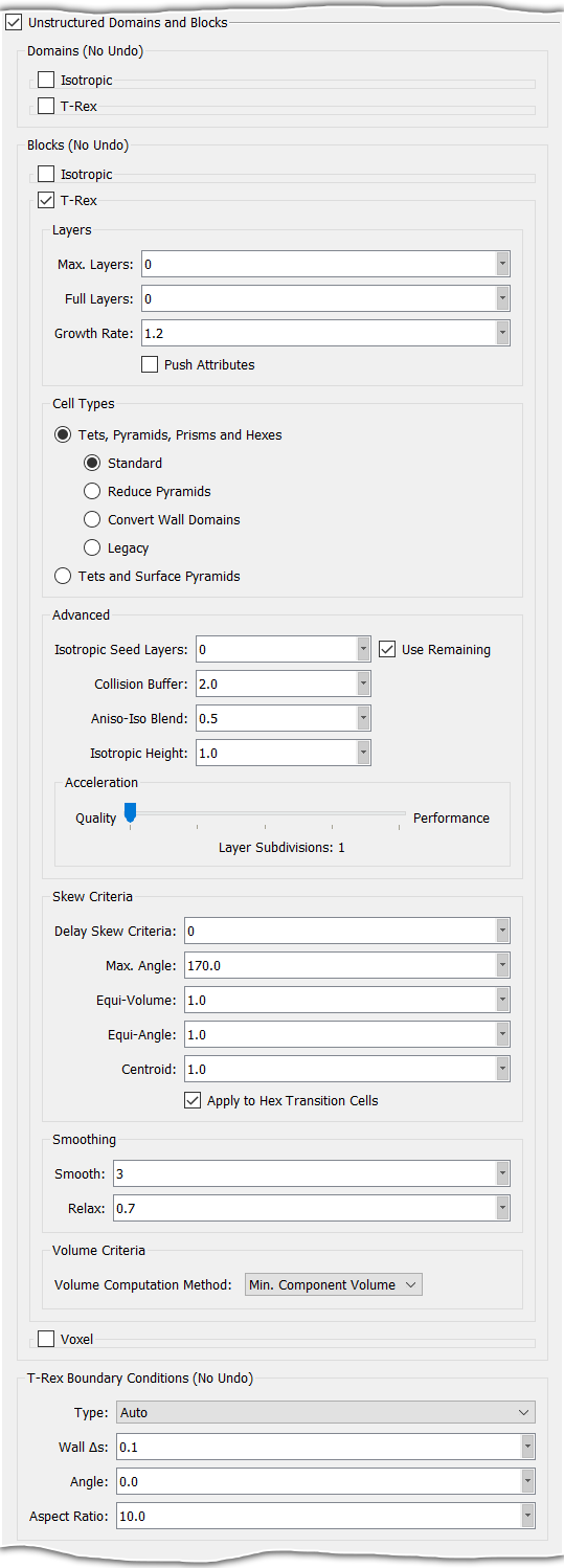
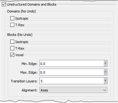
The Blocks frame (shown below) provides default settings for Isotropic tetrahedral cells, for T-Rex attributes, and for Voxel cells. The Isotropic attributes (shown in the left image below) are explained in detail in the Attributes Tab section. The T-Rex attributes (shown in the center image below) are explained in detail in the T-Rex Tab section. Last but not least, the Voxel attributes (shown in the right image below) are explained in detail in the Attributes Tab for voxel blocks and in the Attributes Tab for unstructured blocks where Voxel is the selected Algorithm. Keep in mind that these default setting are only applied to newly created unstructured blocks.

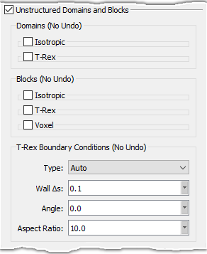
The T-Rex Boundary Conditions frame (shown below) is located at the end of the Unstructured Domains and Blocks frame. This frame contains a drop-down list and three text entry fields. The drop-down list allows you to select a default T-Rex boundary condition type. This default type is automatically assigned to new T-Rex boundary conditions created using the tools in either the 2D T-Rex Boundary Conditions Tab or the 3D T-Rex Boundary Conditions Tab. Furthermore, if the selected default boundary condition type is either Wall, Angle, Aspect Ratio, or Max. Aspect Ratio, this type is also automatically assigned to new T-Rex boundary conditions created by the Apply T-Rex command.
The Auto option in the BC Type list is unique to the Defaults panel. With Auto selected, Off is applied as the default BC when creating new BCs via the Solve command. The Angle field determines which type of BC is applied when using the Apply T-Rex command. If Angle is specified, then an Angle BC is applied when using the Apply T-Rex command, otherwise a Wall BC is applied. The Aspect Ratio field is currently not considered when using the Auto BC Type.
The first text entry field, Wall Δs, allows you to specify a default T-Rex wall spacing value; the second one, Angle, allows you to specify a default 2D T-Rex turning angle value; the third entry field, Aspect Ratio, allows you to specify a default 2D T-Rex aspect ratio value. All these settings are used with newly created T-Rex boundary conditions respectively.
You can find detailed information about T-Rex boundary conditions in the following sections: Boundary Conditions Tab (2D) and Boundary Conditions Tab (3D).
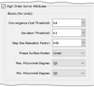
High Order Solver Attributes
The High Order Solver Attributes frame provides default settings for the high-order solver attributes for newly created blocks. These attributes are described in detail on the Elevate Tab sub-section within the Elevate section.
Size Field
The Size Field frame provides general size field default settings, as well as defaults for newly created source entities. Decay, Background Spacing, and Calculation are described in detail for the Size Field tab of the unstructured block Solve command. Information on source Spacing and Decay can be found in the description for the Sources command.
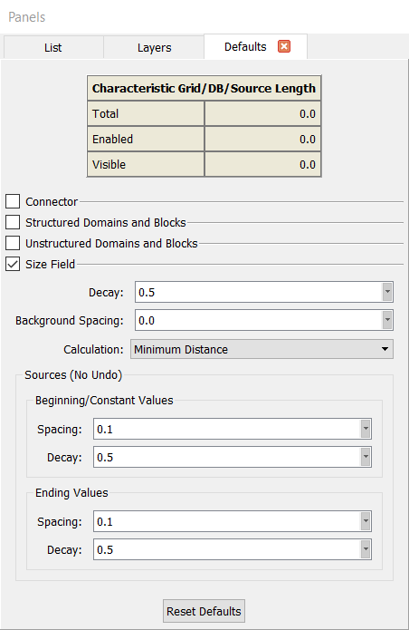
Finally, at the bottom of the Defaults panel is the Reset Defaults command (shown above). Use this command to restore all default settings to those applied for a new project.