Description
The Cutting frame (shown below) provides tools for scanning the interior of block volumes.
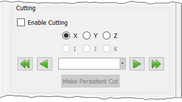
At the top of the frame, Enable Cutting will turn on an active cutting plane which can be used to scanned through the currently selected block(s).
For unstructured blocks, this cutting plane can be an XYZ Cartesian plane (XY, XZ or YZ) or a User Specified cut (explained below). Note that, for clarity, the active cutting plane is rendered slightly larger than the entities being examined. Furthermore, it will have a green border frame and semi-opaque shaded interior making it easier to visualize exactly where the cutting plane intersects the model. The frame of the cutting plane can be clicked and dragged to a new position directly in the Display window. Additionally, the cutting plane can be stepped through the block's volume using the left and right arrow pad arrow keys on the keyboard.
For structured blocks, the cutting plane can be either the same XYZ Cartesian plane as for unstructured blocks, it can be an IJK computational coordinate plane, or it can be a User Specified cut. IJK cutting planes can also be stepped through the block's volume using the left and right arrow pad arrow keys on the keyboard. Note that IJK cutting planes are also available for prism blocks only in the K direction.
Tip: IJK cutting planes allow you to quickly scan through the interior of a structured block(s). This is particularly useful if you have found that you have highly skewed cells or cells with negative volume and need to visualize why such cells are misformed.
The Enable Cutting toggle turns the active cutting planes on and off. Check this box to have the XYZ, IJK (structured blocks only), or User Specified cutting plane rendered. Note that only one type can be active at any given time.
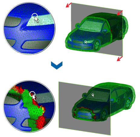
Below the radio buttons, there is a text field surrounded by single and double arrow buttons. The arrow buttons can be used for fine increment scanning and the double arrow buttons for coarse increment scanning. The exact coordinate value (XYZ cutting) or computational coordinate (IJK cutting) can be defined in two ways: it can be entered directly into the provided text field, or it can be specified by selecting a point from the Display window (e.g. a grid point on a block's bounding surface domain, a database entity, a visible overset object, a grid point on a existent examine/persistent cutting plane, or an examine extrema cell). Note that you need to use the Shift+LMB shortcut in order to be able to select a point from the Display window. When doing this, a small circle on the mouse pointer will indicate that a point is ready for selection (shown in the image below).
Tip: You can make a cutting plane slice through a metric's maximum or minimum volume cell by simply rendering these extrema cells and then using the Shift+LMB shortcut to select one of their vertices. This will force the cutting plane to exactly pass through the selected point.
The Make Persistent Cut command will allow you to transform the examine cutting plane being defined into a persistent cutting plane. For more information on persistent cutting planes, review the Create, Cut Planes section.
Note: The Make Persistent Cut command allows you to create persistent examine cutting planes. In contrast with regular examine cutting planes, persistent planes remain visible outside the Examine functionality.