Description
The Boundaries panel provides tools for controlling which boundary edges have 2D T-Rex boundary conditions applied for anisotropic clustering.
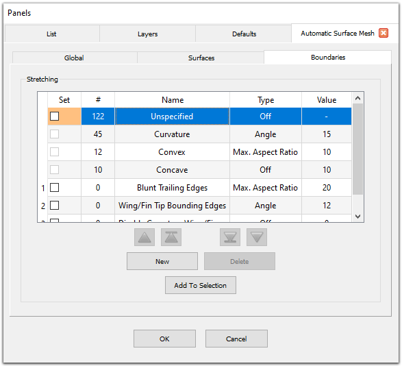
The first four rows in the Stretching table show the default stretching filters used by the Automatic Surface Mesh command to automatically classify boundary edges: Unspecified, Curvature, Convex, and Concave. These filters cannot be deleted or renamed and are automatically placed at a lower priority than user-defined filters. See the Default Stretching Filters section below for more information on which edges are automatically assigned to each default filter.
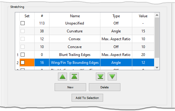
The buttons (New, Delete, Add to Selection,
![]() ,
,
![]() ,
,
![]() , and
, and
![]() ) and
first 4 columns in the table (priority, Set, #, and Name)
all function the same as other filters in the Flashpoint toolset. Please refer to the
Flashpoint Filters section for more information.
) and
first 4 columns in the table (priority, Set, #, and Name)
all function the same as other filters in the Flashpoint toolset. Please refer to the
Flashpoint Filters section for more information.
The remaining columns (Type and Value) are read-only in the Stretching table. Selecting a filter in the table brings up an additional frame that allows you to edit the filter's definition, including the filter's Type, Value, and other more advanced options. See the Stretching Filter Frame section below for more information.
Default Stretching Filters
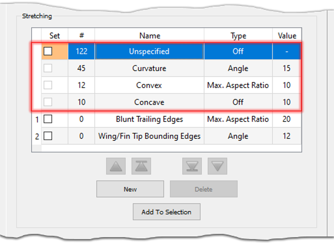
The first four rows of the table in the Stretching frame display the default stretching filters to which Automatic Surface Mesh automatically assigns boundary edges:
- Curvature: Edges are classified as Curvature if the target connector dimension based on surface curvature is much greater than the target dimension based on the curvature of the edge's underlying curve definition (i.e. the edge is straight but the quilts sharing that edge have significant curvature in the direction normal to the edge). The available Type options for the Curvature filter are Angle (default) and Off. The value for the Curvature filter is taken from the Curvature Resolution parameter on the Global tab.
- Convex/Concave: Edges are classified as Convex and
Concave according to both the
Hard Edge Angle
parameter in the Advanced frame on the Global tab and the orientation of
the geometry. If the angle between the quilt normals is greater than the prescribed value,
the edge is classified as Convex (if the normals point away from the boundary) or
Concave (if the normals point toward the boundary). The available Type
options for the Convex and Concave filters are Max. Aspect Ratio
and Off. By default, the Convex filter type is set to Max. Aspect
Ratio and the Concave filter type is set to Off. The values for the
Convex and Concave filters are taken from the
Max. Aspect Ratio parameter on the
Global tab.
Tip: Edges are assigned to Convex and Concave based on the model's normal direction. If these edges are classified opposite to what you expect you can change the model's normal direction by going to Edit, Orient and reversing the normal. When you re-enter Automatic Surface Mesh, the edges should be classified correctly.
- Unspecified: Edges not classified as Curvature, Convex, or Concave are automatically assigned to the Unspecified filter. The columns of this filter are not editable, however the Set checkbox is enabled and can be used to manually assign edges to this filter.
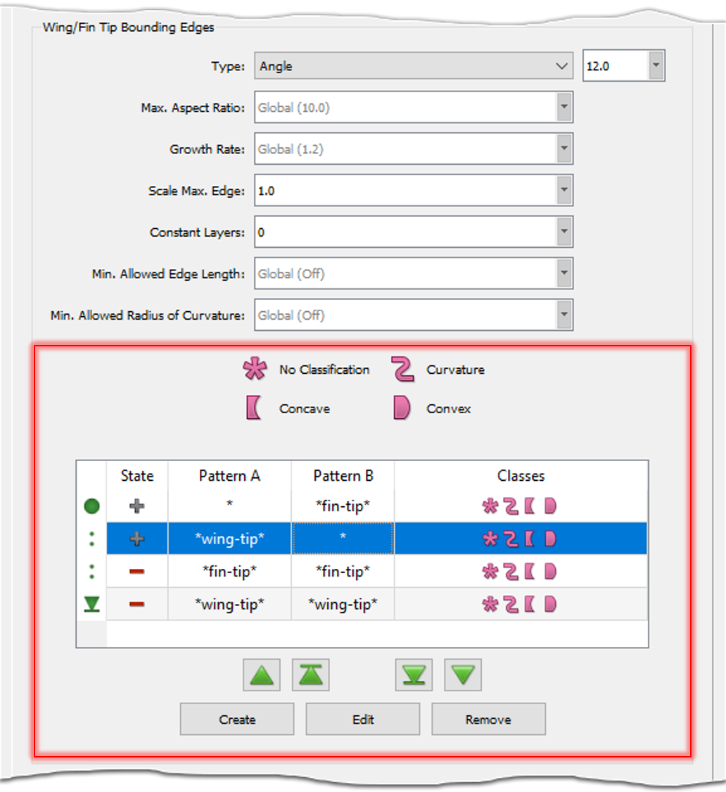
Stretching Filter Frame
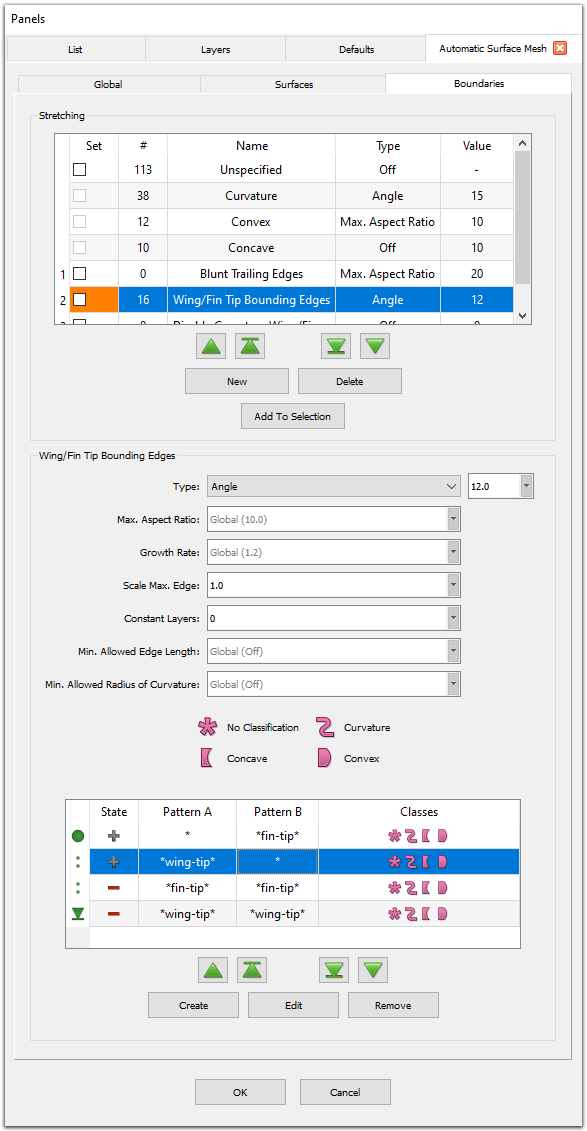
Selecting a stretching filter (other than the Unspecified filter) in the Stretching table brings up a secondary frame with the same name as the selected filter that contains controls for editing the filter definition.
Use the Type pull down list to choose from one of four types:
- Off: Turns anisotropic clustering off for the assigned boundary edges. This is the default setting for newly created filters.
- Angle: Applies anisotropic clustering to the assigned boundary edges using a 2D T-Rex Angle boundary condition. Use the corresponding entry field to specify the desired turning angle resolution (expressed in degrees) for cells along the assigned boundary edges.
- Max. Aspect Ratio: Applies anisotropic clustering to the assigned boundary edges using a 2D T-Rex Max. Aspect Ratio boundary condition. Use the corresponding entry field to specify the desired maximum aspect ratio for resultant surface cells along the assigned boundary edges.
- Explicit: Applies anisotropic clustering to the assigned boundary edges
using a 2D T-Rex
Wall
boundary condition. Use the corresponding entry field to
specify the desired initial height for cells along the assigned boundary edges.
Caution: The Explicit boundary filter type is defined using a dimensional value, meaning that it is tied to a particular geometry and scale. If you plan on re-using your Automatic Surface Mesh settings across multiple similar geometries, it is better to use either the Angle or Max. Aspect Ratio types since they are based on non-dimensional values which will scale appropriately.
The Max. Aspect Ratio parameter provides more fine-tuned control of the mesh resolution in the transverse direction for the Angle and Explicit boundary filter types. By default, Max. Aspect Ratio is set to the value specified on the Global tab (displayed in gray text for convenience). Specify a different value to locally override the global Max. Aspect Ratio for the assigned edges.
The Growth Rate and Constant Layers parameters provide more fine-tuned control of the growth schedule for anisotropic clustering on the filter's assigned edges. By default, Growth Rate is set to the value specified on the Global tab (displayed in gray text for convenience). Specify a different value to locally override the global Boundary Growth Rate for the assigned edges. The Constant Layers parameter allows you to specify an integer number of constant growth layers before the Growth Rate is applied and has a default value of 0.
Note: The Constant Layers parameter tells T-Rex how many layers of anisotropic cells to grow using the prescribed initial spacing before applying the Growth Rate. For a value of 1, T-Rex will grow 1 layer using the initial spacing and apply the Growth Rate to layers >= 2. For a value of 2, T-Rex will grow 2 layers using the initial spacing and apply the Growth Rate to layers >= 3, and so on. The default value of 0 is a special value that indicates that T-Rex should use the legacy behavior. This produces the same result as specifying a value of 1, i.e. the first layer uses the prescribed initial spacing and subsequent layers apply the Growth Rate.
The Scale Max. Edge parameter allows you to scale the edge length for the assigned edges with respect to the settings on both the Global and Surfaces tabs. Scale Max. Edge has a valid range of [0, 1] and the default setting is 0.5 if Type is set to Off and 1 otherwise.
The Min. Allowed Edge Length and Min. Allowed Radius of Curvature parameters allow you specify a minimum edge length and radius of curvature, respectively, for the edges assigned to the boundary filter. These parameters are intended to limit excessive over-refinement due to inconsistencies in the geometry definition and offer a more versatile and targeted approach than the corresponding options on the Global tab because they are only applied locally to the edges targeted by the boundary filter. By default, Min. Allowed Edge Length and Min Allowed Radius of Curvature are disabled (indicated by the word Off displayed in gray text). Enter a value in the corresponding entry field to enable. Note that values may not be fully respected if they conflict with other resolution goals that have been specified.
Note: Automatic Surface Mesh may violate the Min. Allowed Edge Length if the specified value is incompatible with other resolution goals. Min. Allowed Edge Length has an upper bound of Min. Boundary Length / Min. Subdivisions.
It is recommended to check that all of your resolution goals across the Global, Surfaces, and Boundaries tabs are compatible before creating your surface mesh.
Tip: Over-refinement is often the result of issues with the underlying surface curvature in the CAD geometry. The Min. Allowed Radius of Curvature parameter usually offers a better solution over the Min. Allowed Edge Length parameter because it sets a limit on the resolution for these unrealistic curvature values without affecting other regions. Use the Show Surface Curvature command to visualize the surface curvature and determine an appropriate value for Min. Allowed Radius of Curvature.
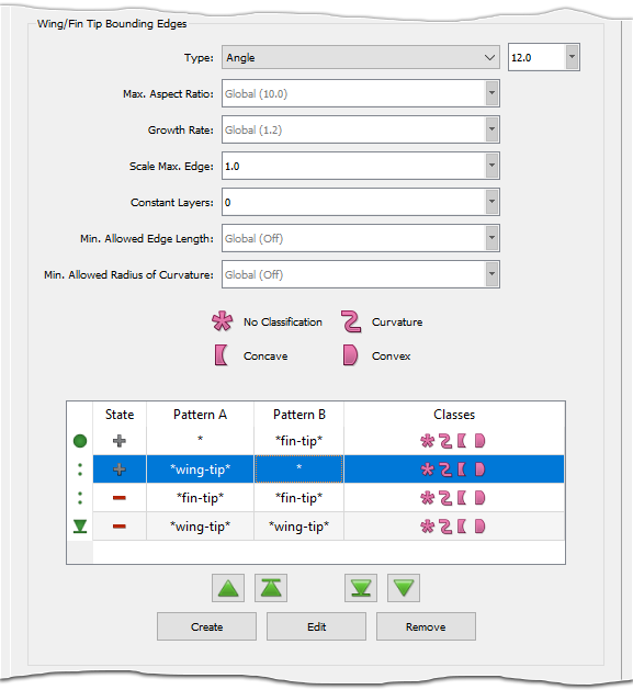
User-Defined Stretching Filter Pattern Sets
Stretching filters are defined by prescribing one or more filter pattern sets. These are displayed in the table in the filter's frame. Use the Create command to create a new filter pattern set or the Edit command to edit the definition of the currently selected pattern set. Pressing either the Create or Edit buttons switches the frame to editing mode. This mode contains fields that can be used to update the pattern set's definition. Use the Save and Discard commands to save and discard your changes, respectively, and exit the editing mode. Use the Remove command to remove the selected pattern set from the filter's definition.
Filter pattern sets are applied in the order in which they appear in the table: the first
pattern set applied is denoted with the begin icon
(![]() )
and the last pattern set with the end icon
(
)
and the last pattern set with the end icon
(![]() ).
The up and down green arrow buttons
(
).
The up and down green arrow buttons
(![]() ,
,
![]() ,
,
![]() , and
, and
![]() ) can be used to move the selected pattern set's position up or down in the table.
) can be used to move the selected pattern set's position up or down in the table.
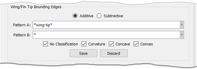
The State column displays an icon denoting whether the filter pattern set is additive
(![]() )
or subtractive (
)
or subtractive (![]() ).
This can be changed in editing mode using the Additive and
Subtractive radio buttons. Additive pattern sets add edges that match the pattern set to the filter's
selection and subtractive pattern sets remove edges that match the pattern set from the filter's
selection.
).
This can be changed in editing mode using the Additive and
Subtractive radio buttons. Additive pattern sets add edges that match the pattern set to the filter's
selection and subtractive pattern sets remove edges that match the pattern set from the filter's
selection.
Tip: Since filter pattern sets are applied in the order in which they appear in the filter pattern table, changing the order of the pattern sets can change which boundary edges are selected by the stretching filter. It is usually a good idea to place all additive pattern sets at the beginning of the list and all subtractive pattern sets at the end.
The Pattern A and Pattern B columns display the patterns for the filter pattern set. These patterns can be specified in editing mode using the corresponding Pattern A and Pattern B fields. The quilts shared by an edge must match both Pattern A and Pattern B for the edge to be selected by the pattern set. Only a single pattern can be specified in each pattern field (i.e. a comma separated list of patterns cannot be specified). To match lamina boundary edges (boundaries belonging to only one quilt), simply leave Pattern B empty. Please refer to the Wildcard Pattern Matching section on the Flashpoint Filters page and the table at the bottom of this page for more information on specifying wildcard patterns.
The Classes column displays the default edge classifications to which the pattern
set is applied. The classifications are No Classification
(![]() ),
Curvature (
),
Curvature (![]() ),
Concave (
),
Concave (![]() ),
and Convex (
),
and Convex (![]() )
and they correspond to the four default stretching filters that edges are automatically assigned
to. The icons are also provided in a legend above the table for reference. While editing the
pattern set, use the four accompanying classification checkboxes to fine-tune which
classifications the pattern set is applied to.
)
and they correspond to the four default stretching filters that edges are automatically assigned
to. The icons are also provided in a legend above the table for reference. While editing the
pattern set, use the four accompanying classification checkboxes to fine-tune which
classifications the pattern set is applied to.
The table below shows several example pattern sets showing the specifications for each of the columns (State, Pattern A, Pattern B, and Classes) along with a description of what the pattern set does.
| State | Pattern A | Pattern B | Classes | Meaning |
|---|---|---|---|---|
upper-* |
lower-* |
|
Any boundaries between any quilt that matches "upper-*" and any quilt that matches "lower-*" regardless of classification will be included. | |
left-* |
right-* |
|
Any convex boundaries shared between any quilt that matches "left-*" and any quilt that matches "right-*" will be included. | |
forward-* |
aft-* |
|
Any boundaries not classified as convex or concave shared between any quilt that matches "forward-*" and any quilt that matches "aft-*" will be included. | |
inner-* |
|
Any lamina boundaries on a quilt that matches "inner-*" will be included, regardless of classification. | ||
outer-*-aft |
|
Any lamina boundaries not classified as curvature, convex, or concave on any quilt that matches "outer-*-aft" will be included. | ||
fuselage-* |
|
Any lamina boundaries not classified as curvature, convex, or concave on any quilt that matches "fuselage-*" will be excluded. | ||
fuselage-* |
* |
|
Any boundaries not classified as curvature, convex, or concave shared between a quilt that matches "fuselage-*" and any other quilt will be included. | |
canard-upper-* |
canard-lower-* |
|
Any boundaries regardless of classification shared between any quilt that matches "canard-upper-*" and any quilt that matches "canard-lower-*" will be excluded. | |
canard-upper-inner |
canard-lower-inner |
|
Any curvature boundaries between the quilts named "canard-upper-inner" and "canard-lower-inner" will be excluded. |