Description
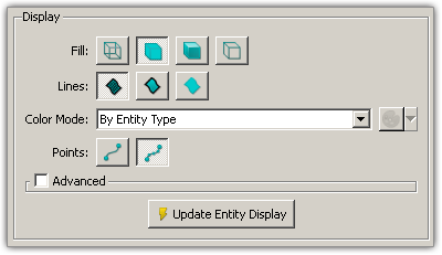
The Display frame (shown below) on the Attributes panel provides tools for choosing exactly how entities are rendered in the Display window. At the bottom of this frame, the Update Entity Display command instructs Fidelity Pointwise to apply the selected render attributes and is only available when changes have been made. This feature allows you to change multiple settings, such as Fill, Lines, Color Mode and Points, and then have these settings all applied at once rather than having the entities updated with each change.
Fill controls the manner in which database surfaces or domains are displayed:
| Icon | Type | Description |
|---|---|---|
| Wireframe | The selected entity or entities will be displayed with only lines representing an entity's edges, cells, isolines, or intervals, depending on the Lines selection (see below). Default for database and grid entities. | |
| Flat | The selected entity or entities will be displayed as a continuous solid surface without lighting effect. Only applies to database surfaces or domains. | |
| Shaded | The selected entity or entities will be displayed as a continuous solid surface with lighting. Only applies to database surfaces or domains. | |
| Hidden Line | The selected entity or entities will be displayed so that only those objects closest to the user along a ray in the z screen coordinate will be visible. Objects that fall behind those closest to the user will be hidden from view. |
Tip: To give your mesh a solid appearance and still be able to see the exterior domain distributions, use the Shaded and Wireframe Display Style on all of your domains.
Lines controls whether boundary or interior lines of the selected database surfaces or domains will be displayed:
| Icon | Type | Description |
|---|---|---|
| All Lines | Both boundary and interior lines will be displayed. | |
| Boundaries | Only boundary lines will be displayed. | |
| No Lines | Neither boundary or interior lines will be displayed. |
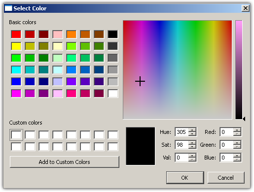
By default, grid entities have their Color Mode set to By Entity Type, applying standard topology-use colors to all grid entities. In this mode, the color selection palette is not available since the colors are predefined. Database entities, on the other hand, have their Color Mode set to Per Entity by default. Therefore, the color selection palette is available. Click on the color box adjacent to the Color Mode pull-down to change the color of a selected entity using a standard color palette tool (shown below). The pull-down arrow next to the color box provides a list of previously used colors to choose from. Previously used colors (to a maximum of ten) are stored, per user, from one session of Fidelity Pointwise to the next so that they are available when returning to Fidelity Pointwise later. The same set of most recently used (MRU) colors will be shown in both the Attributes panel color chooser pull-down and the color chooser pull-down on the Attributes toolbar.
Color Modes available for database and grid entities are as follows:
| Type | Description |
|---|---|
| Per Entity | The selected entity or entities can have their color individually set. Default for database entities. |
| By Entity Type | The selected entity or entities will have their color automatically pre-selected based on type. This is the default for grid entities. Take connectors as an example, bright green and light green are used for displaying undimensioned and dimensioned connectors respectively. If a connector is used in a domain or a block, it is displayed in light blue or dark blue. |
| By Topology | The selected entity or entities will have their color automatically pre-selected based on usage: manifold, non-manifold, or free connections. |
Tip: By default entities are rendered using a By Entity Type Display Mode. This will result in consistent coloring, particularly for connectors where color represents topological use. However, you are free to tailor colors to your specific needs by changing the Mode to Per Entity.
Points controls whether grid points of selected connector(s) or control points of selected database curve(s) will be displayed:
| Icon | Type | Description |
|---|---|---|
| Points Off | Display of the grid points or control points of the selected entities will be turned off. Default for database and grid entities. | |
| Points On | Display of the grid points or control points of the selected entities will be turned on. |