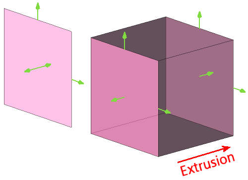
An initial rectangular shape can be created by defining two corner points. Two sets of handles normal to the sides of the initial rectangle can be dragged to change its height and width (see figure below). A third set of handles normal to the initial drawing plane can be dragged to extrude the initial shape, called the "base", in this direction to form a volumetric solid.
The contents and functionality of the Entity Type, Grid Type, Mode and Point Placement frames do not dependent on the type of the shape under construction (a Box in this case). The first three frames are described in the Draw Shapes section; the last one is described in the Point Placement section.
On the other hand, the contents and functionality of the Enclosing Parameters, Shape Parameters, and Shape Options frames are dependent on the type of shape under construction. The Enclosing Parameters frame contains the commands needed to define the characteristics of the shape under construction in Enclosing mode with respect to a set of selected entities being enclosed by the new shape (refer to the Draw Shapes section for more details on the available modes). The Shape Parameters and Shape Options frames contain the commands needed to define the general characteristics of the shape under construction. Here we describe the contents of these three frames for the specific case of a shape of type Box.
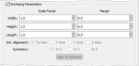
After a shape has been created in Enclosing mode, you can scale it by specified factors using the Scale Factor entry fields. For the case of a box shape, there are entry fields for scaling the shape's Width, Height, and Length, separately. Note that you can only scale the shape to a larger size; this means that the specified factors must be larger than 1.0.
There are also Width, Height, and Length Margin entry fields that allow you to specify a set of margins with respect to the set of selected entities being enclosed by the shape. These margins will effectively increase the size of the shape by the specified amount in each corresponding direction. Note that you can only increase the size of the shape; this means that the specified margins must be larger than 0.0.
The enclosing shape can be aligned in either one of the three coordinate directions using the corresponding radio button: X-Axis, Y-Axis, and Z-Axis. It can also be aligned to the current view if the To View option is selected. Note that the latter option is selected by default. You can also chose whether the enclosing shape is symmetric with respect to the X, Y, or Z direction by selecting the appropriate Symmetry option: In X, In Y, or In Z.
The last command in this frame is Align to Selection. When this button is clicked, Fidelity Pointwise will attempt to determine the primary direction of the enclosed entities and will align the enclosing shape with that direction.
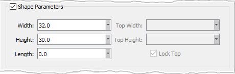
In the Shape Parameters frame, the Width, Height, and Length text fields can be used to precisely set the desired width, height, and length of the box.
The Lock Top command will allow you to resize the base and top surfaces independently. When checked on (default), the height and width of both surfaces are resized simultaneously either by dragging the appropriate handles or by using the Width and Height text fields. On the other hand, when this command is unchecked, the Top Width and Top Height text fields become enabled and can be used to resize the width and height of top surface independently from the base.
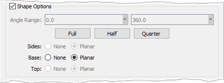
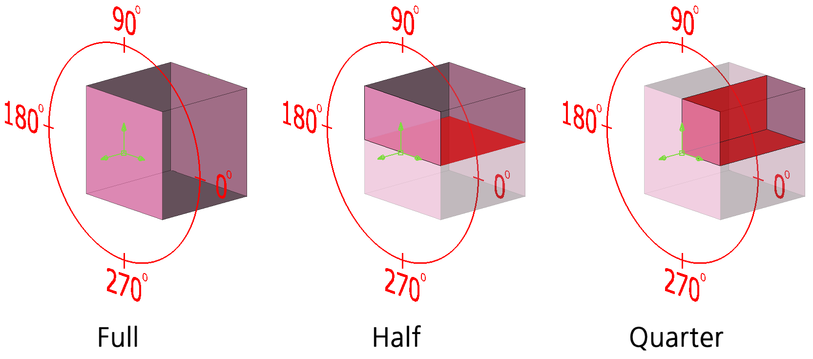
In the Shape Options frame, the Full, Half, and Quarter commands are used to specify whether the full, half, or a quarter of the box under construction should be preserved once the latter is finalized. If the Half option is selected, only the 0° - 180° half of the shape will be preserved. If the Quarter option is selected, only the 0° - 90° quarter of the shape will be preserved. Please refer to the figure below to see how these angles are measured with respect to the local coordinate system (green axes).
Note that you can display the axes for the local coordinate system by selecting the Translate mode (explained in the Draw Shapes section) either via the GUI or by using the T keyboard shortcut.
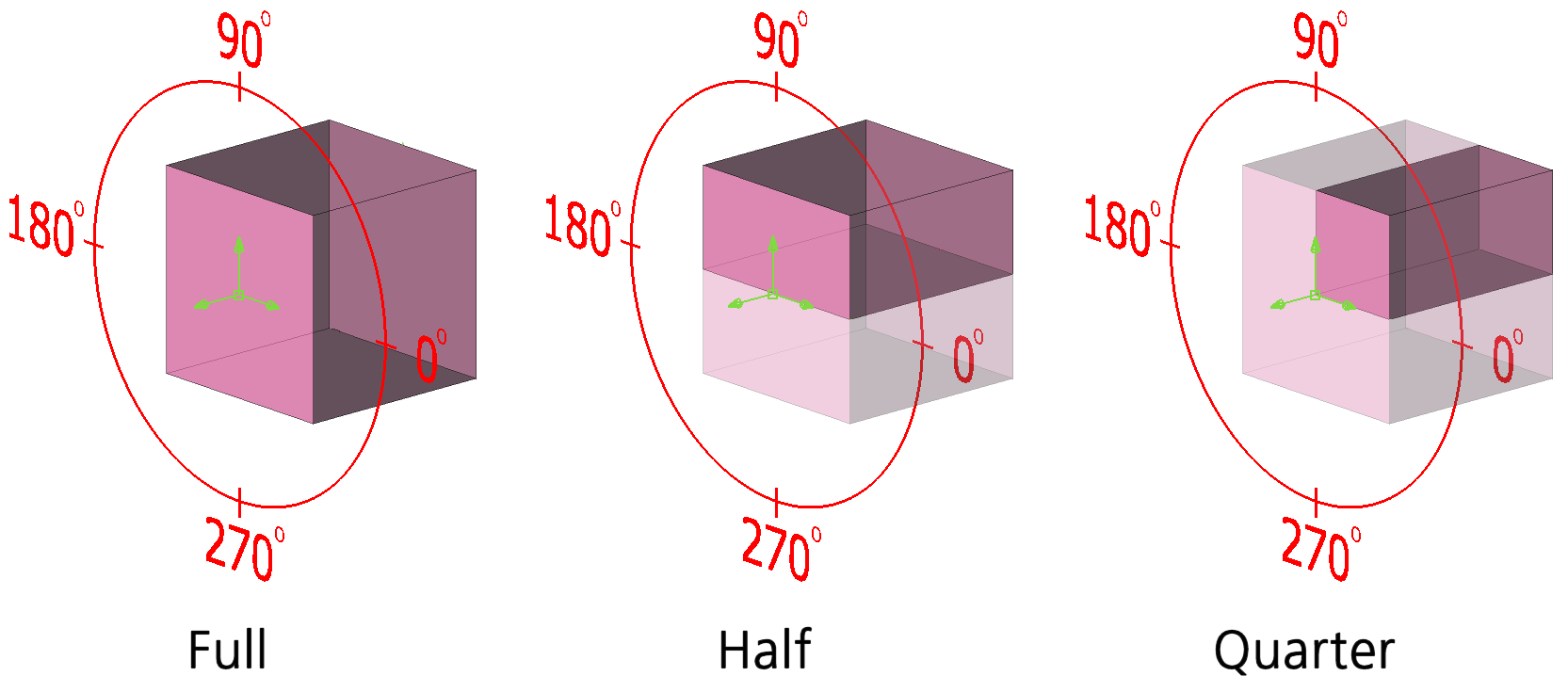
When only a portion of the box under construction is preserved, new sides will be exposed. These new sides are shown in red in the figure below. The Sides, Base, and Top commands are used to specify whether the sides, base, and top planar surfaces should be preserved once the box is finalized. Note that the Sides option will become enabled once new sides are exposed.