Description
The Create, Cut Planes command allows you to create persistent examine cutting planes. In contrast with
regular examine cutting planes, persistent planes remain visible outside the
Examine menu.
Persistent examine cutting planes have the following attributes:
- A single persistent cutting plane can slice through a single block or through multiple blocks.
- All persistent cutting planes can display a single examine metric function at a time.
- Persistent cutting planes can be of type cartesian (XY, XZ, or YZ), computational (I, J, or K), or user specified (i.e. do not align with principal
axes or computational directions).
- Persistent cutting planes are limited in scope to their host framework.
- Cartesian and user specified persistent cutting planes can use the following styles: Crinkle, Cells, or Flat.
- Different persistent cutting planes can use different display attributes. That being said, note that each
cutting plane uses the transparency setting of its host framework.
- The cell stencils and metric-valued colors of persistent cutting planes are automatically updated when any of its associated blocks are updated.
Caution: The cell stencils and metric-valued colors of a persistent cutting plane are automatically updated when the block(s)
associated to the plane is updated. Depending on the size of the associated block(s), this could be a computationally intensive operation.
Use the commands in the Cut Planes menu to define persistent cut planes.
Tip: The visibility and display attributes of existent persistent cutting planes can be controled using the tools in
the Persistent Cuts panel.
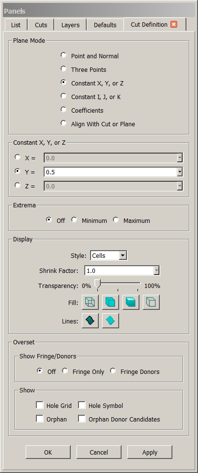
Plane Mode
At the top of the panel, the Plane Mode frame contains several options to specify the manner in which the location of the new persistent cutting
plane will be defined.
- Point and Normal: When using this mode, first select or click a point in the Display window or enter the point coordinates
directly into the XYZ text field. Then enter a directional vector into the Direction text field or choose a primary axis direction
using Use X-Axis, Use Y-Axis, or Use Z-Axis. Note that once the point is placed, it can be edited either graphically in
the Display window or via the XYZ text field.
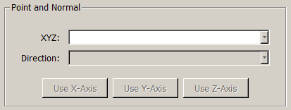
Use the Point and Normal mode to create a cutting plane defined by one point and the plane's normal.
- Three Points: This mode mode simply requires input of three points, either selected or clicked in the Display window, or input
sequentially via the XYZ text field.
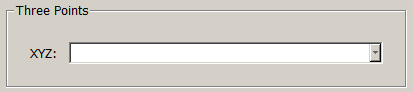
Use the Three Points mode to create a database plane defined by three points.
- Constant X, Y, or Z: Use this mode to create a constant coordinate plane. First choose the coordinate for which you wish to create the
plane. Then enter the coordinate value in the corresponding text field.
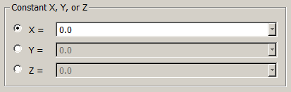
Use the Constant X, Y, or Z mode to quickly create a constant XYZ coordinate plane.
- Constant I, J, or K: Use this mode to create a constant I, J, or K computational cutting plane. First chose the computational coordinate
for which you wish to create the plane. Then enter the coordinate value in the corresponding text field.
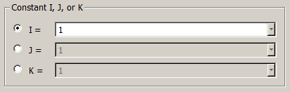
Use the Constant I, J, or K mode to quickly create a computational plane.
- Coefficients: Use this mode to define a plane using the four mathematical coefficients found in the equation of a plane. Simply enter the
coefficients using the provided A, B, C, and D text fields.
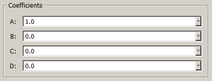
Use the Coefficients mode to define a plane using the four mathematical coefficients found in the equation of a plane.
- Align With Plane: This mode will allow you align the persistent cutting plane being defined with an existent database
plane or persistent cutting plane. After this option is selected, simply chose the desired existent plane and the new persistent cutting plane will
automatically align with it. Note that this option opens up the selection to database and cutting planes that may exist in other
frameworks, thus allowing the opportunity to persistently examine features across frameworks simultaneously.
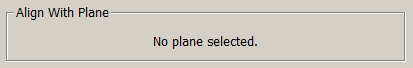
Use the Align With Plane mode align the new cutting plane with an existent
database plane or persistent cutting plane.
Extrema
The Extrema frame contains tools to facilitate the automatic placement of new persistent cutting planes at
the extrema locations of the current examine function. If the Off option is selected (default), the
new plane will be created at the location specified using the tools detailed above. On the other hand, if either the Minimum or Maximum
option is selected, the new plane will be automatically placed in the appropriate extrema location.
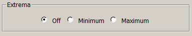
Use the options in the Extrema frame to automatically place the new persistent cutting plane at the
extrema
location of the current
metric function.
Display
The Display frame provides standard tools for choosing the cutting Style (Cells, Crinkle, or Flat) as well as the
display attributes (Shrink Factor, Transparency, Fill and Lines) of the persistent cutting plane being defined. The
different cutting styles and display attributes are described in detail in the Examine, Cutting
and View, Attributes, Display sections respectively.
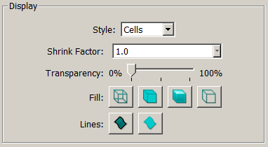
Use the options in the Display frame to define the
cutting style
and
display attributes of the persistent cutting plane being defined.
Overset
The Overset frame contains all the tools needed to control the visibility of the overset data in the persistent cutting plane being defined. This
frame and all its options will be visible only if any of the selected blocks contains overset data.
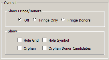
Use the options in the Overset frame to define which overset objects should be shown in the persistent cutting plane being defined.
In particular, the Show Fringe/Donors frame contains several options allowing you to control the visibility of fringes objects and their donors:
| Type |
Description |
| Off |
Fringes/Donors are not rendered. |
| Fringe Only |
Fringes are rendered, but donors are not rendered. |
| Fringe Donors |
Fringes and Fringe Donors are rendered. |
The tools in the Show frame allow you to further customize the visibility of the overset objects:
| Type |
Description |
| Hole Grid |
Show cells removed by the hole cutter during overset grid assembly. |
| Hole Symbol |
Show a hole symbol to represent cells removed by the hole cutter during
overset grid assembly. |
| Orphan |
Show orphan elements. Orphans are fringes which do not have a suitable
donor. |
| Orphan Donor Candidates |
Show orphan donor candidates. |
Keep in mind that The visibility and display attributes of existent persistent cutting planes can be controled using the tools in
the Persistent Cuts panel.
