Description
Check on the checkbox in the Set column to assign the boundary condition in that row to the selected boundaries. Unchecking the checkbox will change the selected boundaries to the Unspecified boundary condition type.
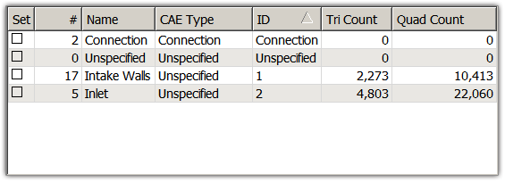
The # column shows how many boundaries are set to the boundary condition in that row.
The Name column shows the boundary condition name. The name can be changed by double-clicking on the boundary condition name you want changed and typing a new name.
Tip: Use boundary condition names to uniquely identify surface regions of the grid for reference in your analysis software. Additionally, volume conditions can be used to identify regions of the grid with different material properties and to uniquely identify different volumes in your analysis software.
Type shows the boundary condition type. The allowable values for Type are different for each CAE Solver. To change the boundary condition type, double-click on the label of the boundary condition type you want to change. This will activate a pulldown list where you can select the desired boundary condition type.
ID is an identification number for each boundary condition that will be passed to the CAE software in the boundary condition file. To change it, double-click on the ID number you want to change and type the new ID number. Fidelity Pointwise does not enforce ID uniqueness. Consult specifications for your selected CAE software to determine appropriate ID values.
Tri Count shows the number of triangle cells assigned to a given boundary condition. Similarly, Quad Count shows the number of quadrilaterals assigned.
The boundary conditions can be sorted by #, Name, CAE Type, ID, Tri Count, and Quad Count. Simply click on the header and the order of the boundary conditions will change accordingly. For example, if you wished to sort all boundary conditions by their names, you would click on the Name header in the Set BC list. The direction of the arrow in the header indicates whether the sort is in ascending or descending order. Fidelity Pointwise also remembers how you prefer to have your boundary conditions sorted. Upon entering the Set BC panel, the boundary conditions will be sorted in the same manner as when you exited the command.
Note that the Name, Type and ID for the Connection and Unspecified boundary conditions are always Connection and Unspecified, respectively. The fields for these boundary conditions cannot be changed. These boundary conditions also remain first and second in the Set BC list and cannot be sorted.