Description
The controls in the Surface Shape frame allow you specify the shape and projection criteria for a given set of unstructured domains.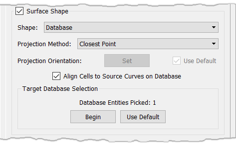
The Shape parameter is used to specify the manner in which the shape of the domain is maintained during solution. The following two techniques are available:
- Free: The shape is computed implicitly as a result of the triangulation method for the Cartesian coordinates (x,y,z). If the domain is constrained to the database and you run the solver with the free shape attribute, the domain will no longer conform to the database. Free is the default shape attribute unless the domain was created directly on a database entity using an automatic method (e.g. Domains on Database Entities). In that case the default shape attribute is Database.
- Database This method is used to conform the domain to one or more database entities. For best results, the starting domain should already lie on the database entities, which can be accomplished automatically when the domain is created or by projecting the domain onto the database later.
Tip: The Free surface shape constraint is quite handy for situations in which you have a domain that you wish to solve just based on the boundary connector dimensions, distribution, and shape. If those boundary connectors are database constrained, the Free surface shape will ignore that association.
The Projection Method parameter determines how grid points are moved onto the database. There are two choices:
- Closest Point: Points are projected to the closest point on the database. This method does not require a projection vector, so the Projection Orientation options are disabled.
- Linear: Points are projected along a fixed vector. The Projection Orientation parameter provides options for setting the projection vector.
Note: The projection type selected for the Edit, Project command will be stored as an attribute of a domain so that when using Grid, Solve, the Projection Method will default to the same.
The Projection Orientation parameter is used to set the projection vector for the Linear projection method. The Set command is used to set the projection vector perpendicular to the Display window (screen-z). Check the Use Default check box to indicate that the default projection direction should be used. The default orientation is computed by averaging the domain's normal vector at each grid point.
When the Align Cells to Source Curves on Database option is checked on, the unstructured domain solver will align the isotropic cells in a database constrained domain to the general direction defined by a source curve constrained to the same database surface. Note that anisotropic T-Rex cells will not be affected by this command. Generally speaking, this command provides a way to capture interior edges (features) in unstructured domains without the need to create baffle edges. Note that for this option to work as intended, both the domain and the source curve(s) need to be constrained to the same set of database surfaces.
Tip: Unstructured domains can contain baffle edges. In other words, they can contain an edge that has no area. To form a baffle edge, select a single connector twice to form the edge and click Save Edge. These baffle edges can be used to gain point distribution control on the interior of an unstructured domain as well as being used as a true baffle in a 2D grid set as a wall type BC.
The Align Cells to Source Curves on Database option is enabled by default. The alignment effect of a particular source curve can be turned off by hiding the curve in question (refer to the Show Hidden section for further information on hidden entities) or by disabling the source on the Size Field Tab. On the other hand, the alignment effect of all source curves can be turned off at once by unchecking the Align Cells to Source Curves on Database.
The tools within the Target Database Selection frame allow you to select the target projection database entities from all those currently visible.
Tip: When using the Surface Shape parameter, it is important to make sure that the database surfaces you wish to solve your grid on are all selected within the Target Database Selection frame.
After the Begin button is pressed, you can select database entities from either the List panel or the Display window. The current set of target entities is already picked when the button is first pressed. The button remains depressed with the text End now displayed. Pressing End stops selection of projection database entities.
Use Default means the grids will be projected onto the default set of database entities. The default database entities are computed for each grid based on which entities are currently referenced by the grid points.