Description
The Break Points tab provides tools for adding and removing break points on the interior of your connectors. A legend appears at top defining the symbols used to represent different types of break points:
- Circles: Represent break points at the ends of a connector.
- Squares: Represent fixed break points.
- Diamonds: Represent arc length based break points.
A fixed break point is defined by selecting an existing control point and is tied to that control point’s physical coordinates regardless of subsequent changes to the arc length of the connector. Arc length break points are defined either visually or via type in at some percentage of connector arc length and always maintain that percent location regardless of subsequent changes to the arc length of a connector. Subsequent deletion of a control point will also delete a fixed break point at that location.
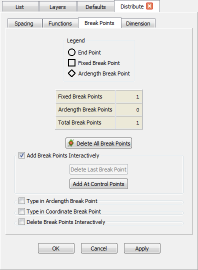
A table summarizes the number of each type of break point and the total for reference. Delete All Break Points provides convenient access to the popular capability, also available on the Grid toolbar, allowing one click removal of all interior break points. Three collapsing command frames are available on this tab, but only one can be open at any given time, thus restricting the currently available commands. The default frame is Add Break Points Interactively. This option allows you to define break points by simply clicking on locations anywhere along the connector length or by direct selection of a grid point or control point. Use Delete Last Break Point or the Delete shortcut on the keyboard to remove the most recently defined break point. Add At Control Points will place a new break point at each control point along the connector interior.
Tip: See the View, Toolbars, Customize command for more on adding Delete All Break Points and other commands to your Grid toolbar.
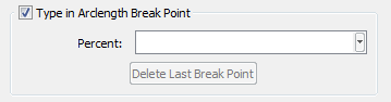
Open the Type in Arclength Break Point frame to access direct text entry of a connector percent arc length for break point location.

Open the Type in Coordinate Break Point frame to access direct text entry of Constant X, Constant Y, or Constant Z values for break point location. Multiple break points will be created if a connector is multi-valued in the entered coordinate. If the entered value is outside the extents of the connector, no break point will be created. Additionally, you can enter Constant U or Constant V values for database constrained connectors. Use Delete Last Break Point or the Delete shortcut on the keyboard to remove the most recently defined break point.
Tip: Very often we find ourselves joining connectors together in order to produce a continuous distribution of grid points. When doing this, Fidelity Pointwise preserves the original connector distributions by inserting break points at the location of every removed connector node. This behavior can be changed via settings in the Connector, Distribution command frame in the Defaults panel.
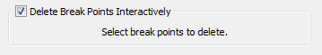
Open the Delete Break Points Interactively frame to have current selection changed to picking individual break points in the Display window. Every break point selected in the Display window will be immediately removed from the connector and the point distribution will be updated accordingly.