Description
The Properties command allows you to see the total lengths of the current database, grid, and sources as well as specify what tolerances should be associated with the current project. The total lengths of your current grid, database, and sources can be a useful measure in determining the initial default dimensions for your connectors as well as what tolerances should be used for your project.
Three lengths are reported in the Characteristic Grid/DB Length table to assist you in determining appropriate tolerances:
- Total is the maximum extent of all grid and database entities, regardless of layer or show/hide status.
- Enabled is the maximum extent of all shown grid and database entities, regardless of layer status.
- Visible is the maximum extent of all shown grid and database entities in layers that are on.
The extents for each of the lengths are calculated as the maximum edge length of the bounding box that encloses the entities and the origin.
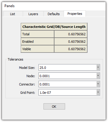
Project tolerances are displayed in the Tolerances frame. These tolerances are an important aspect of your project file. They control how grid entities are logically connected across gaps in the database and the way many database creation and intersection operations perform.
Model Size
The Model Size tolerance serves as the basis for all tolerances used for Fidelity Pointwise's geometric computations. Examples of such computations are intersections, projections, and the triangular surface mesher.
Note: The Model Size tolerance affects many calculations within Fidelity Pointwise including, but not limited to, intersections and projections. If you ever encounter problems getting the intersection curves or projection you think you should, it may be an indication that you need to see if you have a reasonable Model Size tolerance set for your project.
Because the Model Size is used as the basis for Fidelity Pointwise's geometric computations, it is important to set it to a value on the same order of magnitude as your geometry extents prior to importing the geometry. Examples of the tolerances computed from the Model Size tolerance are shown in the table below.
| Tolerance Type | Formula | Default Value |
|---|---|---|
| Model Size | L | 1000 |
| Same-point | L/107 | 0.0001 |
| Surface-fit | L/106 | 0.001 |
Tip: For most grids, the default tolerances set in the Properties panel work well. However, you should really consider adjusting the Model Size if your overall model or grid size are several orders of magnitude larger than the default Model Size tolerance.
Node
The Node tolerance is the real value within which two nodes are considered identical. Applying a new node tolerance will cause the entire grid system to be updated based on the new value. Any formerly distinct nodes falling within the new tolerance will be combined.
The importance of this tolerance lies in the fact that it is used to determine whether two connectors are end-to-end adjacent and thus can be used within a domain. This tolerance is also used by the Grid, Merge command.
The default value is 0.0001.
Note: Since changing the Node tolerance in File, Properties has global impact on your mesh, it is usually better to use the Merge command to overcome node mismatches since Merge allows you to choose what to merge.
Connector
The Connector tolerance is the real value within which two connectors with equal, non-zero dimensions are considered identical. To determine if they are within tolerance, the distances between grid points along the connectors are computed. If the maximum distance between corresponding grid points is less than the connector tolerance, the connectors are considered identical. One connector will be deleted and replaced with the other.
Applying a new connector tolerance will cause the entire grid system to be updated based on the new value. Any formerly distinct connectors falling within the new tolerance will be combined.
The default value is 0.0001.
Tip: If you find yourself consistently working with geometry that contains surface gaps larger than the Connector tolerance, it may be worthwhile to increase the Connector tolerance. A tolerance larger than the gaps will help prevent regular coincident connectors.
Grid Point
The Grid Point tolerance is the real value within which two grid points are considered identical. This tolerance is used to determine where singularities (poles) exist in the grid to avoid divide by zero conditions during the computation of various grid control parameters.
The default value is 1.0e-7.