Once created, the periodic connector (or domain) and the original counterpart become slaved periodically. That is, any future changes to one of them (i.e., transformation, redimension, redistribution, etc.) will be reflected in its twin. The only exception to this is the display attributes of a periodic pair can be different.
Note that the Periodic command is only available when the original selection does not have a periodic twin. This is because the periodicity is enforced in pairs: no more than two connectors or two domains may be periodic with each other.
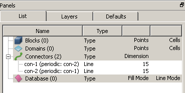
The periodicity information is available in the List panel through entity names. As shown in the figure below, in parentheses next to each periodic connector there is a periodic tag and a name indicating its twin. If either of these two connectors is deleted (or joined), the periodicity will be broken immediately and the other will remain in place.
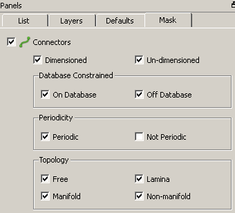
To facilitate the selection of periodic entities in a grid system, check the Periodic checkbox in the Mask panel. This creates a pick mask such that only periodic entities may be selected.
Note that the Periodic command does not automatically assign a periodic boundary condition to a periodic pair of domains (3D) or connectors (2D). If supported by your current CAE solver, periodic boundary conditions must be set via the CAE, Set Boundary Conditions command.