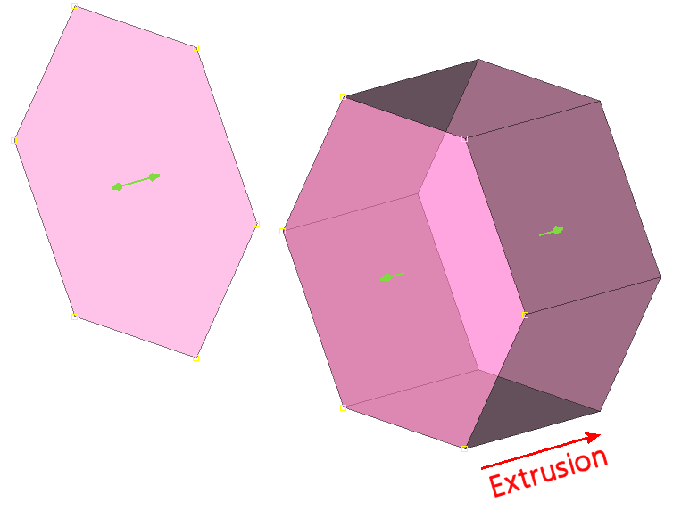
A general polygonal shape can be created starting from an opened or closed curve defined by segments of Linear, Catmull-Rom, Akima, or Bezier type (refer to the Line section for further details). The initial curve or surface, called the "base", can then be extruded by dragging the provided handles to form a surface or a volumetric solid respectively.
The contents and functionality of the Entity Type, Grid Type, Mode and Point Placement frames do not dependent on the type of the shape under construction (a Polygon in this case). The first three frames are described in the Draw Shapes section; the last one is described in the Point Placement section.
On the other hand, the contents and functionality of the Enclosing Parameters, Shape Parameters, and Shape Options frames are dependent on the type of shape under construction. The Enclosing Parameters frame contains the commands needed to define the characteristics of the shape under construction in Enclosing mode with respect to a set of selected entities being enclosed by the new shape (refer to the Draw Shapes section for more details on the available modes). The Shape Parameters and Shape Options frames contain the commands needed to define the general characteristics of the shape under construction. Here we describe the contents of these three frames for the specific case of a shape of type Polygon.
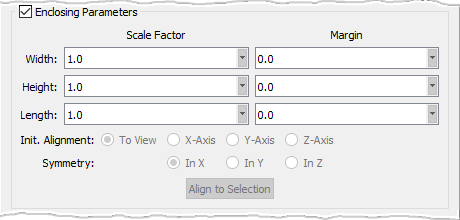
After a shape has been created in Enclosing mode, you can scale it by specified factors using the Scale Factor entry fields. For the case of a polygonal shape, there are entry fields for scaling the shape's Width, Height, and Length, separately. Note that you can only scale the shape to a larger size; this means that the specified factors must be larger than 1.0.
There are also Width, Height, and Length Margin entry fields that allow you to specify a set of margins with respect to the set of selected entities being enclosed by the shape. These margins will effectively increase the size of the shape by the specified amount in each corresponding direction. Note that you can only increase the size of the shape; this means that the specified margins must be larger than 0.0.
The enclosing shape can be aligned in either one of the three coordinate directions using the corresponding radio button: X-Axis, Y-Axis, and Z-Axis. It can also be aligned to the current view if the To View option is selected. Note that the latter option is selected by default. You can also chose whether the enclosing shape is symmetric with respect to the X, Y, or Z direction by selecting the appropriate Symmetry option: In X, In Y, or In Z.
The last command in this frame is Align to Selection. When this button is clicked, Fidelity Pointwise will attempt to determine the primary direction of the enclosed entities and will align the enclosing shape with that direction.

In the Shape Parameters frame, the Linear, Catmull-Rom, Akima, and Bezier options (refer to the Line section for further details) will allow you to set the slope control algorithm to be used when creating the curves defining the base polygonal shape.
The Lock Normal To Base command is used to define the extrusion direction. When checked on (default), the direction remains normal to the base shape to be extruded. Otherwise, the extrusion direction remains normal to the initial drawing plane.
The Force Planar option forces all the control points to be coplanar; the plane containing these points is defined by the first three control points specified.
The Close Polygon option is used to indicate if the polygonal base defined by the specified control points should be opened or closed. When this option is checked on, the polygonal base will be closed; otherwise, it will be opened.
The Length text field can be used to set a precise extrusion length.
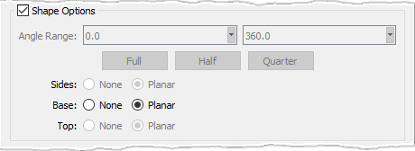
For a polygonal shape, the only commands enabled in the Shape Options frame are Base and Top. These commands are used to specify whether the base and top planar surfaces are to be preserved once the shape is finalized. Note that these commands will be disabled if the base and top surfaces are not planar (Force Planar option unchecked).