Select Create, Draw Curves. A submenu (shown below) is provided to choose from a list of all the available segment
types: Line (![]() ), Curve (
), Curve (![]() ), Line on Database (
), Line on Database (![]() ), Curve on Database (
), Curve on Database (![]() ), Circle (
), Circle (![]() ), Conic (
), Conic (![]() ),
and Pole (
),
and Pole (![]() ). This will be the default segment type applied when the Draw Curve panel opens. Define the
necessary points for the new curve to be created.
). This will be the default segment type applied when the Draw Curve panel opens. Define the
necessary points for the new curve to be created.
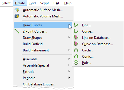
Tip: Use Draw Curves when more efficient topology creation tools, such as 2 Point Curves and Connectors on Database Entities, do not fit the task at hand.
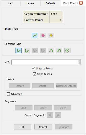
At the top of the Draw Curve panel you will find a table which lists the Segment Number currently in work and the number of Control Points currently defined for that segment.
Below the summary table, you will find the Entity Type frame with options to define the type of curve to be created:
Connector (![]() ), Database (
), Database (![]() ),
or Source (
),
or Source (![]() ).
).
In the Segment Type frame, there are buttons representing all the supported segment
types: Line (![]() ), Curve (
), Curve (![]() ), Line on Database (
), Line on Database (![]() ), Curve on Database (
), Curve on Database (![]() ), Circle (
), Circle (![]() ), Conic (
), Conic (![]() ),
and Pole (
),
and Pole (![]() ). Simply click a Segment Type button to choose that type for the current segment under
construction.
). Simply click a Segment Type button to choose that type for the current segment under
construction.
Below the Entity Type frame, we present the standard options to explicitly specify the points that will define the curve being created:
- XYZ: Enter the XYZ coordinates of the control points defining the curve being created.
- Snap to Points: If checked on, this option allows you to specify the points defining the curve by picking any selectable point
directly on the Display window. Snapping is taking place when a bullseye cursor is displayed (
 ).
).
- Slope Guides: This option allows you to ensure that the curve being created is tangent/perpendicular to an existing curve or normal to a database surface. For detailed information on how this command works for each supported Segment Type, please select the desired type from the options listed at the end of this section.
- Points: This frame contains the following options to restore and delete the control points in the curve being created: Restore, Delete, and Delete All Interior. These standard options are explained in detail in the Point Placement section. Note that the Delete key on your keyboard can be used as a shortcut for the Delete command in this frame.
- Advanced: This expandable frame contains the following less frequently used options by which the location of the two points defining the linear curve can be specified: XYZ Offset, UV, UV Offset, Normal Offset, and Projection. These standard options are explained in detail in the Point Placement section.
The Segments frame provides controls related to entire curve segments. At least two points are required to define a single segment, except when creating a pole, which requires only one point. When starting a new curve, after one point is defined, the Delete command becomes active. This command will remove the current segment from the curve. If it is the only segment, the curve will be cleared. Once two points have been defined, the Segments Add and Insert commands also become active. Segments Add will save the existing segment and move to defining a new segment at the end of the existing segment. Segments Insert will save the existing segment and move to defining a new segment at the beginning of the existing segment. Saving portions of a curve as different segments allows you to use a different segment Type for each segment. This provides the ability to create very complex curve shapes.
The Current Segment arrow command buttons allow you to navigate through the segments in a curve either toward the beginning or end of the curve under construction. Since the Draw Curves command allows you to edit the curve under construction at any time, the Current Segment control allows you to navigate to some other segment to edit it if necessary.
When the new curve is complete, click OK to save it and close the panel, click Cancel to discard it and close the panel, or click Apply to save it and continue on to the next new curve.
For more information on the available Segment Types, choose a topic below: