Description
The tools contained in the Geometry Characteristics frame are designed to visualize the geometric characteristics of the selected database models to be meshed. Furthermore, these tools allow you to not only review the numeric values of such characteristics but also to render them and to zoom in or out to clearly visualize them.
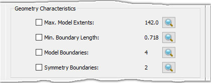
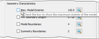
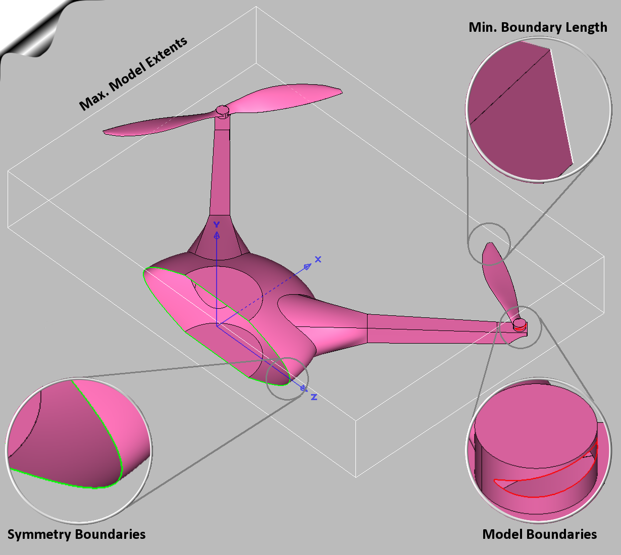
The Max. Model Extents parameter reports the maximum extents of the selected database models. If the corresponding checkbox is checked on, a white box encompassing all of the models and aligned with the principal planes is rendered in the Display window in wireframe style. This box represents the extents of the selected database models.
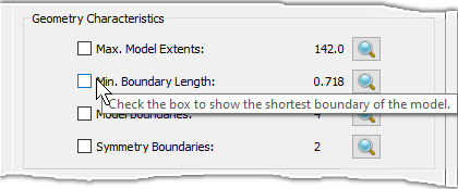
The Min. Boundary Length parameter reports the minimum boundary length in the selected database models. If the corresponding checkbox is checked on, the corresponding edge is rendered in white in the Display window.
Tip: The Min. Boundary Length is usually a small feature and
may be difficult to see while viewing the full geometry. You can click the magnifying lens
(![]() ) or hover the mouse over the value to zoom into a characteristic.
) or hover the mouse over the value to zoom into a characteristic.
The Model Boundaries parameter reports the number of lamina boundaries in the selected database models. Lamina boundaries correspond to surface edges used by exactly one database surface. If the corresponding checkbox is checked on, the lamina boundaries are rendered in red in the Display window. For more information on lamina boundaries, please review the Models section in this User Manual.
The Symmetry Boundaries parameter reports the number of symmetry boundaries in the selected database models. Symmetry boundaries are lamina boundaries that form a closed loop and are contained on one of the principal planes within a symmetry tolerance. If the corresponding checkbox is checked on, these boundaries are rendered in green in the Display window.
Note: It is important to note that the extent box displayed by the Max. Model Extents command is always aligned with the primary planes. Likewise, the Symmetry Boundaries command can only detect symmetry boundaries that are aligned with one of the primary planes.
A few additional tools common to all the geometry characteristics parameters detailed above
are designed to aid in their visualization. The magnifying lens
(![]() )
enables you to zoom in or out to clearly visualize the appropriate characteristic. Additionally,
hovering your mouse over the label with the name of a parameter displays a tool tip with
pertinent information. Last but not least, hovering your mouse over the label with the value of
a parameter renders the parameter (as discussed above) in the Display window and zooms
in or out for clear visualization.
)
enables you to zoom in or out to clearly visualize the appropriate characteristic. Additionally,
hovering your mouse over the label with the name of a parameter displays a tool tip with
pertinent information. Last but not least, hovering your mouse over the label with the value of
a parameter renders the parameter (as discussed above) in the Display window and zooms
in or out for clear visualization.