Description
The Advanced frame provides several additional advanced parameters for controlling the characteristics of the resulting surface mesh including parameters for identifying hard edges and mappable surfaces, refining the surface mesh, and determining which boundaries are considered for domain adaption.
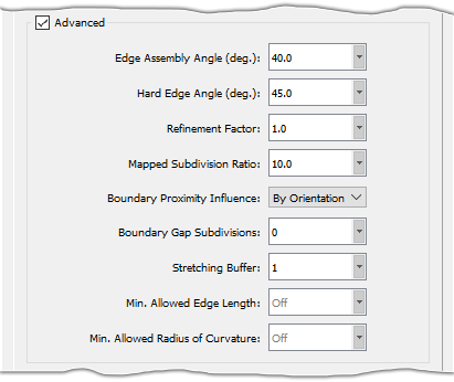
The Edge Assembly Angle parameter is the angle (prescribed in degrees) used to determine whether or not to join connectors when generating the surface mesh. This parameter has a default value of 40.0 and a valid range of [0, 180).

Note: Changing the Edge Assembly Angle may affect how boundaries are reported in the Geometry Characteristics frame. For example, if the new value for Edge Assembly Angle causes the smallest boundary edge to be joined when connectors are built, Min. Boundary Length in the Geometry Characteristics frame is updated accordingly.
The Hard Edge Angle parameter is the angle (prescribed in degrees) used to determine whether the edge between two quilts represents a convex or concave edge. This parameter has a default value of 45.0 and a valid range of [0, 180). If the angle between the quilt normals is greater than the prescribed value, the edge is classified as Convex (if the normals point away from the boundary) or Concave (if the normals point toward the boundary). For more information about Convex and Concave edges, please see the section on the Boundaries Tab.
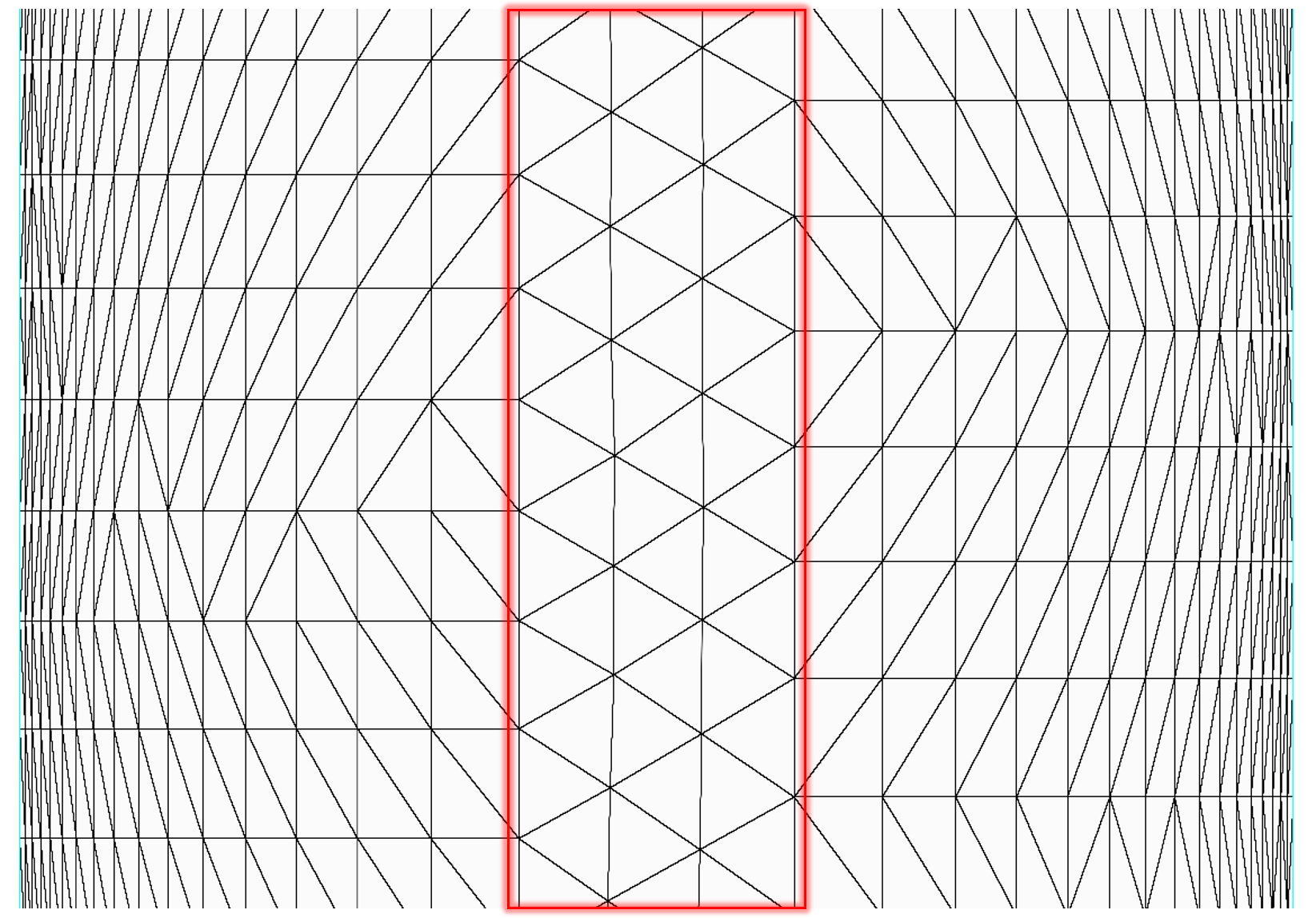
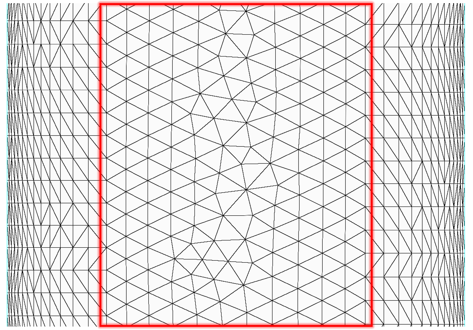
The Refinement Factor parameter is used to globally refine or coarsen the surface mesh. This parameter has a default value of 1.0 and a valid range of [0.125, 8].
Tip: The Refinement Factor can be used to quickly generate surface meshes for an entire mesh family. Once you are satisfied with the quality of the surface mesh, use factors < 1 to generate coarser surface meshes and factors > 1 to generate finer surface meshes.
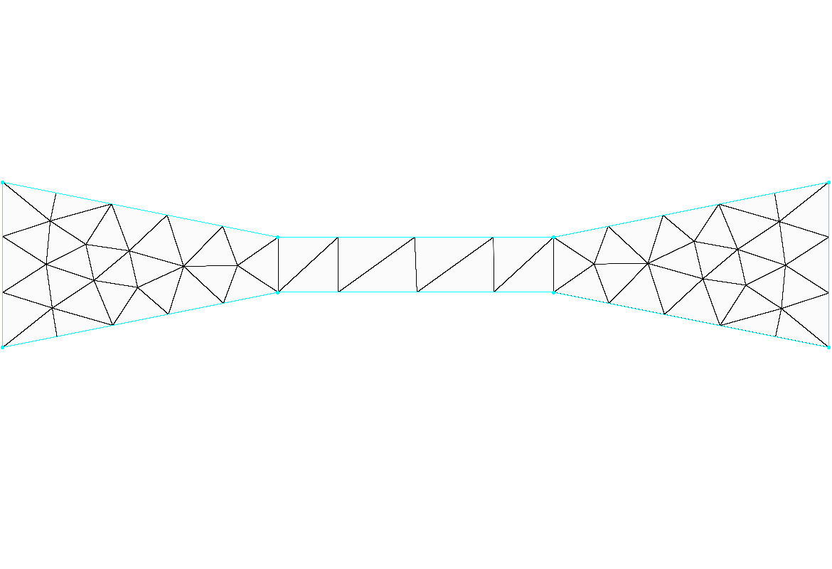
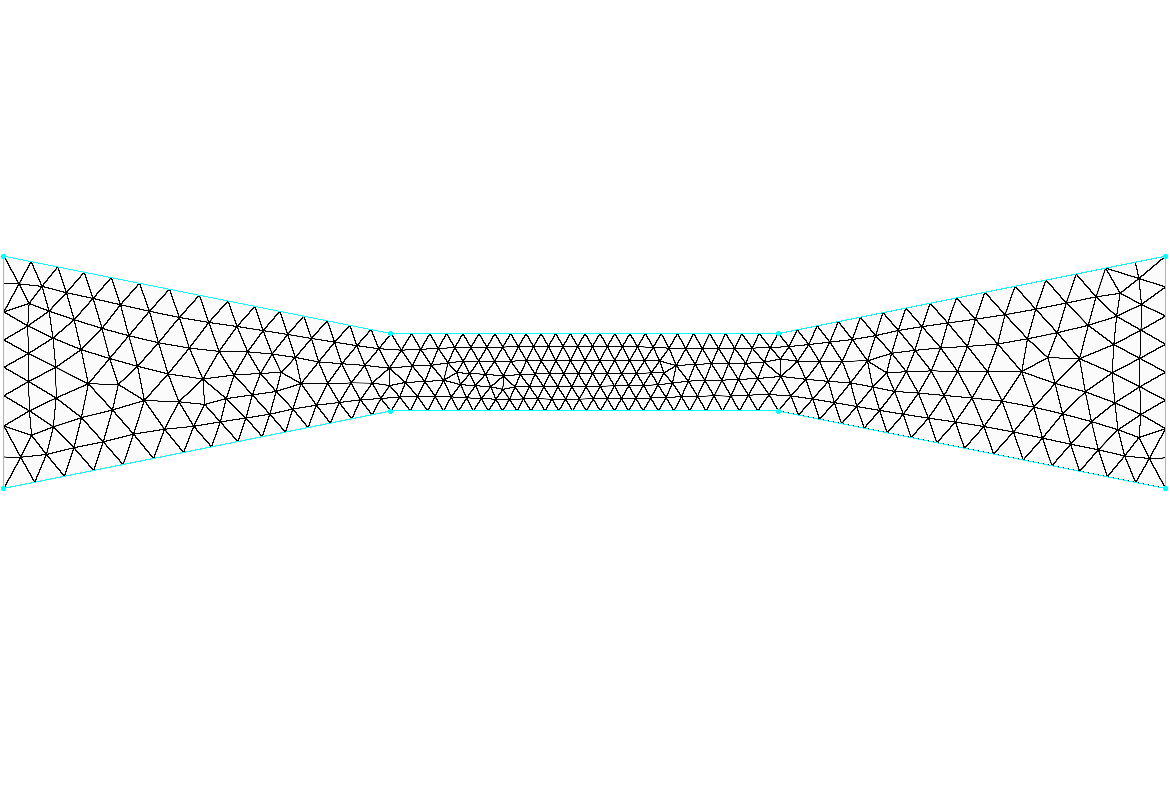
The Mapped Subdivision Ratio parameter is used to identify thin surfaces for special mapped mesh handling (i.e. surfaces for which the unstructured domain should be mapped to an underlying structured domain). This parameter has a default value of 10.0 and a valid range of [0, ∞), where a value of 0 disables thin surface meshing.

The Mapped Subdivision Ratio parameter is defined as the ratio of the subdivisions of the long and short connectors for unstructured domains defined by four connectors. If the computed ratio is greater than the defined value, the connector distributions and dimensions are synced to create a balanced structured domain. The structured domain is then diagonalized with the Link option enabled using either the Best Fit or Keep Quads diagonalization methods, depending on the Algorithm setting in the Goals frame. For more information on domain diagonalization, please review the description of the Diagonalize command in this User Manual.
Tip: After the Create Surface Mesh command is finished, you can hover the mouse over the surface mesh for more information about whether the surface received mapped treatment or not. This information is displayed in the probe area of the Status Bar. Please refer to the Understanding Why A Surface Doesn't Get Mapped section for a list of possible probe messages related to mapped surfaces.
The Boundary Proximity Influence parameter controls which connectors become sources for domain adaption and has three options:
- By Orientation: Only connectors on the outward side of a domain's quilt are used as sources for domain adaption. This option is useful for preventing undesired clustering from connectors on the opposite side of the model and is the default option.
- All: All nearby connectors are used as sources for domain adaption.
- None: No connectors are used as sources for domain adaption.
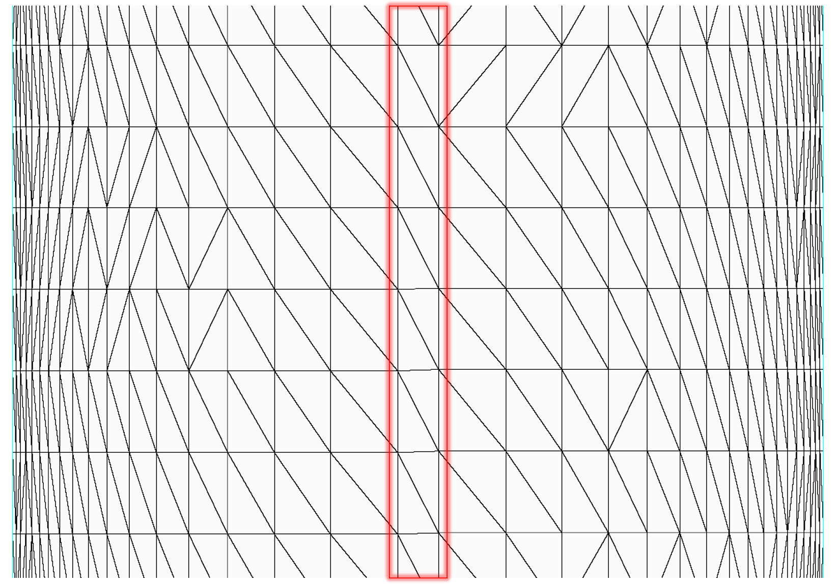
The Boundary Gap Subdivisions parameter specifies the target number of subdivisions used to bridge the gap when Automatic Surface Mesh detects boundaries that lie in close proximity to one another. This parameter has a default value of 0 and a valid range of [0, ∞).
Similarly, the Stretching Buffer parameter specifies the target number of subdivisions to serve as a buffer when T-Rex stretching reaches the median between boundaries. This parameter has a default value of 1 and a valid range of [0, ∞).
Caution: Min. Allowed Edge Length and Min. Allowed Radius of Curvature are intended to limit over-refinement due to issues with the underlying geometry definition. They are not intended to be used as a way of removing small features or closing gaps in the geometry. These types of issues need to be addressed in the model before running Automatic Surface Mesh.
Please refer to the Assemble, Models and Assemble, Quilts sections of this User Manual for more information on preparing your geometry for Automatic Surface Mesh.
The Min. Allowed Edge Length and Min. Allowed Radius of Curvature parameters allow you to specify a global minimum edge length and global minimum radius of curvature in the resultant surface mesh. These parameters are intended to limit excessive over-refinement on the boundaries due to inconsistencies in the geometry definition. Min. Allowed Edge Length and Min. Allowed Radius of Curvature are disabled by default (indicated by the word Off displayed in gray text). Enter a value in the corresponding entry field to enable. Note that values entered may not be fully respected if they conflict with other resolution goals that have been specified.
Note: Automatic Surface Mesh may violate the Min. Allowed Edge Length if the specified value is incompatible with other resolution goals. Min. Allowed Edge Length has an upper bound of Min. Boundary Length / Min. Subdivisions.
It is recommended to check that all of your resolution goals across the Global, Surfaces, and Boundaries tabs are compatible before creating your surface mesh.
Tip: Over-refinement is often the result of issues with the underlying surface curvature in the CAD geometry. The Min. Allowed Radius of Curvature parameter usually offers a better solution over the Min. Allowed Edge Length parameter because it sets a limit on the resolution for these unrealistic curvature values without affecting other regions. Use the Show Surface Curvature command to visualize the surface curvature and determine an appropriate value for Min. Allowed Radius of Curvature.
You can also apply both of these parameters to individual boundary edges using the stretching filters on the Boundaries tab, giving even finer control over where these limiters are applied.