Description
The Advanced panel presents additional advanced parameters to control the
characteristics of the surface mesh to be created, including controls to enable/disable 2D T-Rex
for specific boundary types.
The Advanced panel provides additional, more advanced controls over the characteristics of the
surface mesh being created.
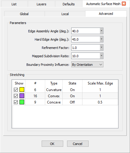
Parameters
The
Parameters frame provides several additional parameters to control the
characteristics of the resulting surface mesh.
The Parameters frame provides additional parameters for identifying hard edges and mappable
surfaces, refining the surface mesh, and determining which boundaries are considered for
domain adaption.
The Edge Assembly Angle parameter is the angle (prescribed in degrees)
used to determine whether or not to join connectors when generating the surface mesh. This
parameter has a default value of 40.0 and a valid range of [0, 180).
Note: Changing the Edge Assembly Angle may affect how
boundaries are reported on the Global tab. For example, if the new
value for Edge Assembly Angle causes the smallest boundary edge to be joined when
connectors are built, Min. Boundary Length in the Geometry
Characteristics frame on the Global tab is updated accordingly.
The Hard Edge Angle parameter is the angle (prescribed in degrees) used
to determine whether the edge between two quilts represents a convex or concave edge. This
parameter has a default value of 45.0 and a valid range of [0, 180). If the angle between
the quilt normals is greater than the prescribed value, the edge is classified as Convex (if
the normals point away from the boundary) or Concave (if the normals point toward
the boundary).
The Refinement Factor parameter is used to globally refine or coarsen
the surface mesh. This parameter has a default value of 1.0 and a valid range of [0.125, 8].
Tip: The Refinement Factor can be used to quickly generate
surface meshes for an entire mesh family. Once you are satisfied with the quality of the
surface mesh, use factors < 1 to generate coarser surface meshes
and factors > 1 to generate finer surface meshes.
The Mapped Subdivision Ratio parameter is used to identify
thin surfaces for special mapped mesh handling (i.e. surfaces for which the unstructured
domain should be mapped to an underlying structured domain). This parameter has a default
value of 10.0 and a valid range of [0, ∞), where a value of 0 disables thin surface
meshing.
The Mapped Subdivision Ratio parameter is used to identify surfaces that are good candidates
for using mapped unstructured domains. The images show the difference between using a mapped
domain (left) and an unmapped domain (right) for the blunt trailing edge of a wing.
The Mapped Subdivision Ratio parameter is defined as the ratio of the subdivisions of the
long and short connectors for unstructured domains defined by four connectors. If the computed
ratio is greater than the defined value, the connector distributions and dimensions are synced
to create a balanced structured domain. The structured domain is then diagonalized with the
Link option enabled using either the Best Fit or Keep Quads
diagonalization methods, depending on the Algorithm setting on the
Global tab. For more information on domain diagonalization, please
review the description of the
Diagonalize command in this User Manual.
After the Create Surface Mesh command is finished, hovering the mouse over the
domains displays information about whether or not the domain is mapped in the probe area of the
Status Bar. Domains that are mapped
also display the computed subdivision ratio while domains that are unmapped show information
about why it was classified as such. Please click the Mapped Domain Probe Messages
button below to view a table showing the possible probe messages that could be displayed as well as
their meanings.
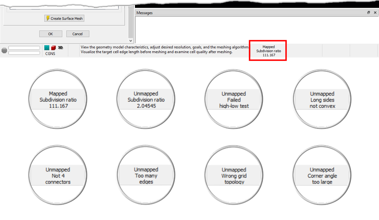
When you hover over domains while in the Automatic Surface Mesh command, the probe area of the
status bar (red rectangle) displays information about whether or not that domain is mapped. This
image shows a selection of the more common messages. Click on the Mapped Domain Probe Messages
button below to see a complete list of all messages.
The Boundary Proximity Influence parameter controls which connectors
become sources for domain adaption and has three options:
- By Orientation: Only connectors on the outward side of a domain's quilt
are used as sources for domain adaption. This option is useful for preventing undesired
clustering from connectors on the opposite side of the model and is the default option.
- All: All nearby connectors are used as sources for domain adaption.
- None: No connectors are used as sources for domain adaption.
The Boundary Proximity Influence determines which connectors (if any) influence clustering on the
interior of domains. Use the By Orientation option (shown left) to prevent undesired
bleed-through clustering that can sometimes result from using the All option (shown right).
Stretching
The table in the Stretching frame provides controls for viewing, enabling/disabling,
and refining the three different classified boundary types: Curvature, Convex,
and Concave. Edges are classified as Curvature edges if the target
connector dimension based on surface curvature is much greater than the target dimension based
on the curvature of the edge's underlying curve definition (i.e. the edge is straight
but the quilts sharing that edge have significant curvature in the direction normal to the
edge). Connectors created on edges classified as
Curvature are automatically assigned to an Angle T-Rex boundary
condition.
Edges are classified as Convex and Concave according to the
Hard Edge Angle parameter in the Parameters frame above.
Connectors created on edges classified as Convex and Concave are automatically assigned
to a Max. Aspect Ratio T-Rex boundary condition. For more information on 2D T-Rex boundary
conditions, please review the
2D T-Rex Boundary
Conditions page in this User Manual.
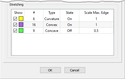
The Stretching frame provides tools that allow you to visualize, enable/disable, and adjust
the refinement of the three types of classified boundaries.
The Type and # columns display read-only values showing the name of the
classified boundary type and the number of connectors associated with that type, respectively.
Use the Show column to enable/disable the display of each classified type. By default,
the checkboxes are checked on and the connectors are rendered in the Display window
using the corresponding color in the Show column. Uncheck the checkbox to disable the
display of a classified boundary type.
The State column allows you to specify whether 2D T-Rex is enabled/disabled for a
particular classified boundary type during the creation of the surface mesh. By default,
Curvature and Convex are turned On and Concave is turned
Off. Click in the State field of a row to bring up a drop-down menu that can
be used to toggle the State On or Off.
The Scale Max. Edge column allows you to scale the edge length for a classified
boundary type with respect to the settings on both the Global and
Local tabs. Scale Max. Edge has a valid range of [0, 1] and
the default setting is 1.0 if the State of the boundary type is On and 0.5
if Off.