Description
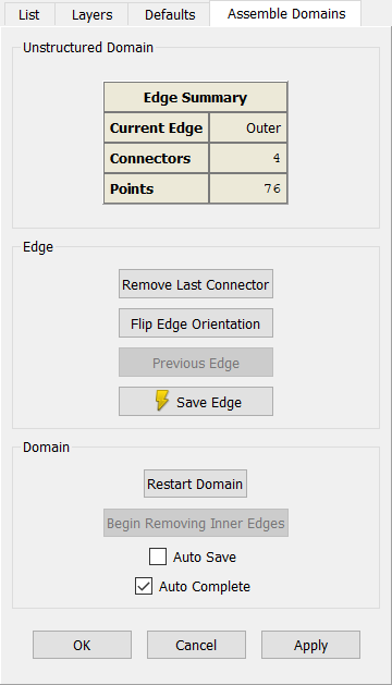
Manual domain assembly proceeds by creating each of the unstructured domain edges individually. Use Create, Assemble Special, Domain to open the Assemble Domains panel shown below. Pick the connectors sequentially in the Display window which form a single edge. When the edge is complete, use Next Edge to save the definition of that edge and move on to the next, if necessary.
Note: The Create, Assemble Special, Domain command automatically overrides the Mask so that only connectors can be picked.
There are a number of commands available during manual unstructured domain assembly which are described here in detail.
Unstructured Domain Frame
The Unstructured Domain frame is used to display an Edge Summary table for the edge under construction. The table lists the Edge number in work, the number of Connectors used, and the total number of Points on the edge. Note that edge 1 is always referred to as the Outer edge.
Tip: The Create, Assemble Special, Domain command will always need to be used for creating unstructured domains with holes, unless the domain can be created on a trimmed database surface with holes using the On Database Entities command.
Edge Frame
The Remove Last Connector command removes the previously added connector from the definition of the domain.
Flip Edge Orientation reverses the direction of the current edge.
Previous Edge drops any definition of the current edge and reverts control to the previous edge in the domain. Use this command when you discover an error or omission in your previously defined edge.
Use Save Edge to save the definition of the current edge and move on to the next.
Tip: Note that the Next Edge button contains a lightning bolt (![]() ). This means
that you can use the Ctrl+F shortcut to quickly perform this operation.
). This means
that you can use the Ctrl+F shortcut to quickly perform this operation.
Domain Frame
Restart Domain throws out all edges for the domain currently under construction and returns to defining the first edge.
The Begin Removing Inner Edges command becomes enabled when the domain being defined has at least one interior (i.e. inner) edge. To remove an inner edge, click Begin Removing Inner Edges and select the edge or edges to be removed. Finish by clicking End Removing Inner Edges.
The Domain frame includes two toggled options allowing additional functionality. Auto Save introduces an automatic Apply so that as soon as the current edge loop is complete, the domain is initialized and saved. This option will preclude addition of any interior edges if used during construction of the Outer edge. Auto Save is turned off by default.
Auto Complete, the second option included in the Domain frame, is on by default. When Auto Complete is checked, the Assemble Domains tool will attempt to complete the entire edge loop automatically after the first connector is selected. Afterward you are immediately placed back at defining the outer edge of an additional domain.
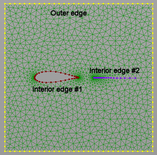
When assembling a unstructured domain with interior edges, start with the definition of the outer edge followed by the interior ones. Note that the interior edges must be oriented in the opposite direction of the outer edge. To define an edge (i.e., "Interior edge #2" in the figure below) based on free standing connector(s), such connectors have to be selected twice to form a closed loop.